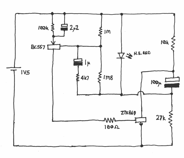
In operation, the 100μF capacitor charges until the voltage at the junction of the 1M and 1M8 resistors is sufficient to turn on the BC557. This then turns on the ZTX869, which pulls the positive end of the 100μF capacitor down to ground. Positive feedback around the two transistors, aided by the 1μF capacitor and 4k7 resistor, ensures a sharp transition between states. With the positive end of the 100μF capacitor pulled down to ground, the sum of the battery voltage and the capacitor voltage appears across the LED and provides enough voltage to flash it. As the 100μF capacitor discharges, and the 2μ2 capacitor charges, the BC557 runs out of base drive and the circuit reverts to the off state, again with positive feedback ensuring a sharp transition.
The value of 100k for the emitter resistor of the BC557 is not a mistake. The function of this resistor is not to supply emitter current, which is supplied by the 2μ2 capacitor, but to discharge the 2μ2 capacitor while the circuit is in the off state in readiness for the next cycle.
The ZTX869 transistor is a high-gain, low-saturation-voltage device (typical Vce(sat) of 50mV at 1A, according to the ZTX869 datasheet) from Zetex. It should not be replaced with a generic device. While it is possible to get something like a BC547 to work, its higher saturation voltage compared with the Zetex device will knacker the circuit's efficiency and it will only give a weedy flash.
The ZTX869 can sometimes be hard to find; it did go out of production at one point (whereupon I bought the whole of Farnell's remaining stock while I still could), but this now (April 2024) appears to have been remedied. At least, it is listed on the "Diodes Inc" website in a manner which certainly makes it look as if it is currently in production, unless there is some stupid hidden element on that page which is supposed to tell me it isn't but doesn't in fact work; and Farnell now list it as "no longer stocked" rather than as "no longer manufactured", whereas I am fairly sure that it was listed as the latter when I bought that remaining stock. I have also found this product change notice, which suggests that it did indeed go out of production for a while at about the right sort of date while they changed to getting it made somewhere else, but started being produced again in 2017. (I don't know if there's a more up-to-date one because you can't get the product change notices off the actual "Diodes Inc" website, you can only find ones that some more helpful person has copied to some other site.)
The same manufacturing technique for achieving a very low Vce(sat) was also used for other transistors in the ZTX range, and for the overlapping FMMT surface-mount range. The ones from these ranges with the lower values for Vceo are a good place to start looking for alternatives. I am also told that some Chinese-manufactured transistors of nominally unpromising types can in fact turn out to have anomalously low Vce(sat)s, so if you have a pile of such devices it might be worth measuring what they give.
It has also been suggested to me that 2SD965, 2SD5041, 2SC2500, SS8050(?) are potentially viable replacements - haven't tested them myself; apparently the 2SD965 is/was a popular choice for the flash inverter in disposable cameras, dead cameras being available from the store for the asking and containing both a 2SD965, and other potentially useful parts like the inverter magnetics for unrelated experimentation.
The circuit is designed for red LEDs as the original "Pulse" LED is red. For yellow or green LEDs with their higher forward voltage, the 1M8 resistor should be increased to provide a higher trip point (though this may compromise performance on a nearly-flat battery), and it is also advantageous to increase the 100μF capacitor to 220μF and scale the 10k and 27k resistors accordingly. For blue and white LEDs it is necessary to cascade two output stages to obtain enough voltage.